LiDAR underpins autonomous perception and high-precision optical sensing by converting reflected light into distance and motion data. As applications demand longer range, direct radial-velocity measurement, and stronger interference resilience, conventional Time-of-Flight (ToF) systems are increasingly complemented by Frequency-Modulated Continuous-Wave (FMCW) LiDAR. This transition raises the requirements for optical modulation.
Thin-Film Lithium Niobate (TFLN), an emerging electro-optic material, combines fast, linear modulation with low optical loss and compact integration, making the TFLN modulator a strong candidate for scalable, high-performance FMCW systems.
How Do LiDAR Requirements Change from ToF to FMCW?
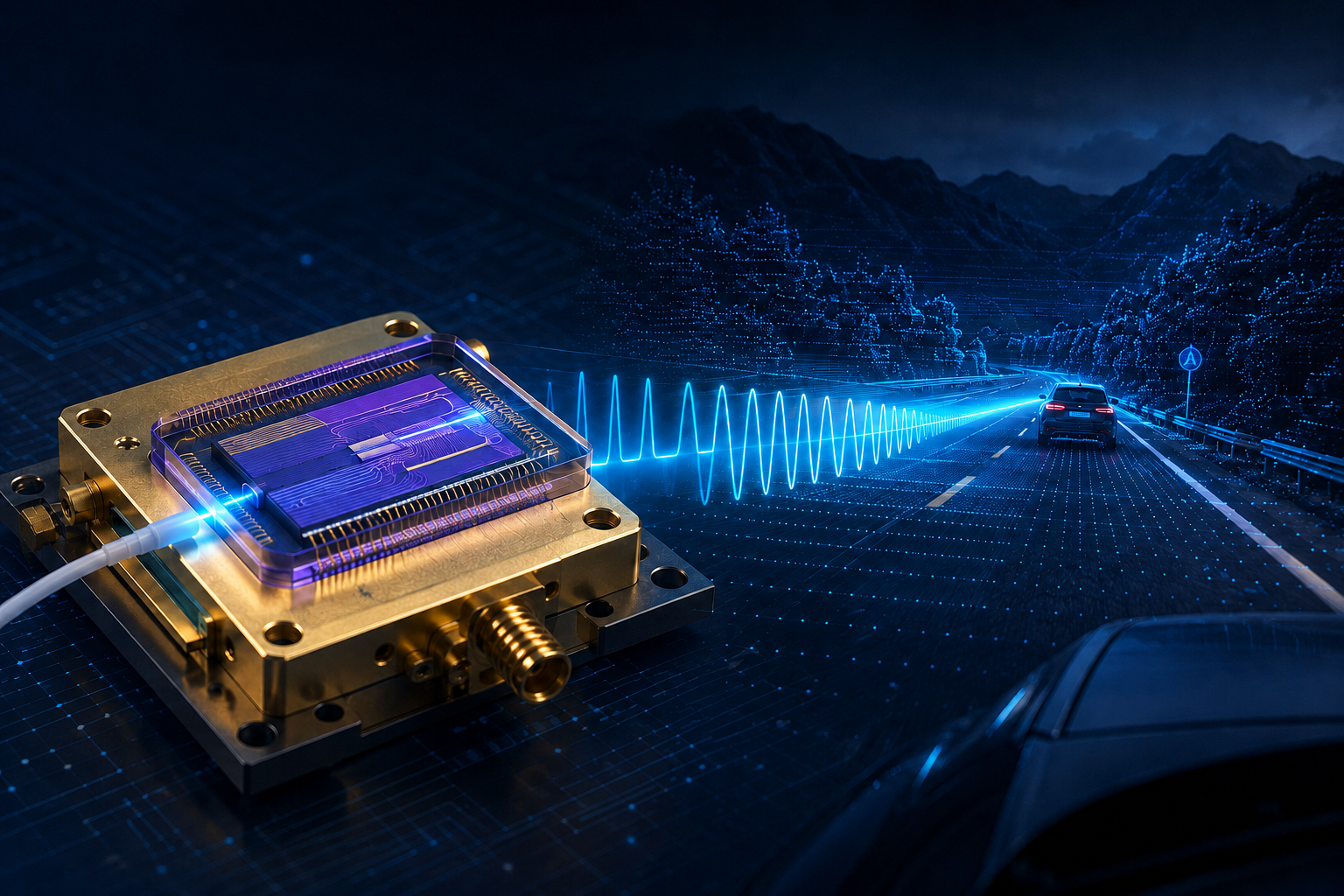
Time-of-Flight (ToF) LiDAR sends short optical pulses and calculates distance from their round-trip delay. FMCW LiDAR transmits continuously chirped light instead. When the return is mixed with a local oscillator, the resulting beat frequency provides range information, while Doppler shift provides radial velocity.
The table shows how this change reshapes the transmitter and receiver requirements.
Design dimension | ToF LiDAR | FMCW LiDAR |
Signal and range method | Short pulses; range from return time | Continuous frequency sweep; range from beat frequency |
Velocity information | Usually inferred across frames | Direct radial velocity from Doppler shift |
Detection approach | Direct detection | Coherent detection with a local oscillator |
Transmitter priorities | Pulse energy and timing precision | Narrow linewidth, linear chirp, low phase noise, and stable modulation |
Moving to FMCW therefore places stricter demands on the modulation stage. Instead of shaping short optical pulses, the transmitter must preserve a controlled frequency sweep with low loss and stable phase. Bandwidth, phase behavior, and drive efficiency consequently become central to the size and performance of the coherent optical engine.
How Does a TFLN Modulator Work in LiDAR?
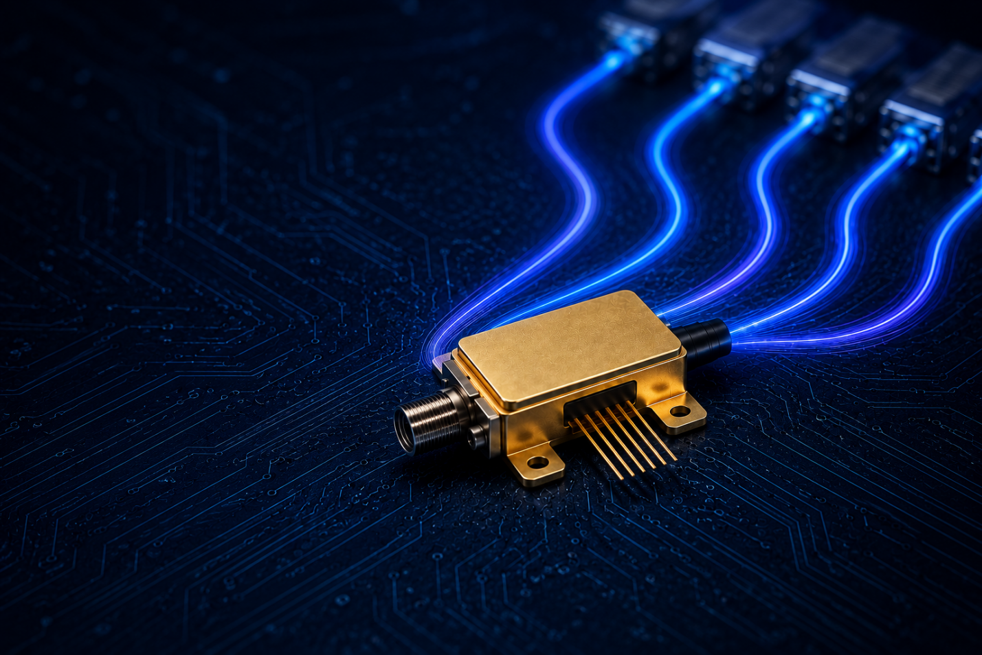
TFLN combines lithium niobate's linear Pockels effect with tightly confined thin-film waveguides. An applied voltage changes the refractive index, allowing a TFLN modulator to translate an electrical waveform into controlled optical intensity or phase.
Typical TFLN devices used for LiDAR include:
Device | How it controls light | Typical LiDAR role |
Mach-Zehnder intensity modulator | Differential phase in two interferometer arms is converted into output-power change | Optical power control, gating, and waveform shaping; phase control in push-pull or nested architectures |
Phase modulator and EO comb generator | A phase modulator changes optical phase directly; a comb creates multiple coherent optical lines | FMCW chirp generation, frequency control, and parallel or multi-wavelength transmitters used with coherent detection |
Put simply, the Mach-Zehnder device controls how optical power is launched and shaped, while phase modulators and comb generators build the frequency and phase structure FMCW requires. This functional split ties device selection to the optical architecture, not bandwidth alone.
Why Do TFLN Modulators Matter for FMCW LiDAR?
Once the device roles are clear, TFLN's value can be identified as four system-level outcomes:
l Cleaner chirps support more precise ranging. The linear electro-optic response helps reproduce the intended frequency sweep, while low added phase noise keeps the beat signal narrow for clearer range and velocity estimation.
l Bandwidth headroom supports faster waveform control. A wide EO response allows the modulator to follow faster electrical sweeps with less roll-off, supporting more agile chirp waveforms.
l Lower loss and drive voltage protect the power budget. Low insertion loss preserves transmit and local-oscillator power. A lower half-wave voltage also reduces the required driver swing and its associated thermal burden.
l Compact integration supports scalable, stable sensors. Thin-film waveguides reduce the active footprint and support multi-channel integration. Shorter optical and RF paths also make phase matching and packaging easier to control.
These advantages apply to autonomous driving sensor systems, mobile robots, aerial-mapping platforms, industrial inspection, and precision optical sensing. Across these applications, compact coherent transmitters support the detection of weak returns while managing optical power and heat.
What to Consider When Designing and Sourcing TFLN Modulators
Selecting a TFLN modulator requires three linked decisions: define the device metrics that preserve the FMCW waveform, choose an integration and packaging architecture for the operating environment, and verify that the supplier ecosystem can support development and scaling. These three areas must work together for the modulator to move from component qualification to a practical FMCW optical engine.
1. Translate FMCW Goals into Device Specifications
Specification | Why it matters | What to evaluate |
EO bandwidth | Ability to follow the target electrical sweep | S21 response across the intended waveform and RF interface |
Chirp linearity and phase noise | Beat-signal width, range precision, and velocity estimation | End-to-end results under the target chirp and bias conditions |
Insertion loss and coupling efficiency | Transmit and local-oscillator optical budgets | On-chip loss, fiber-chip coupling, polarization sensitivity, and repeatability |
Vπ·L and drive compatibility | Device length, voltage swing, and electrical power | Vπ·L at the stated test frequency, electrode impedance, CMOS output range, and linearity |
Once the signal budget is defined, those targets must be preserved through photonic integration and the package.
2. Preserve Performance Through Integration and Packaging
l Build the photonic platform around the required functions. Heterogeneous integration can place TFLN modulators alongside silicon or SiN routing and beamforming circuits. Lasers, detectors, and optical phased arrays can then be integrated at wafer level or co-packaged within the same photonic engine, reducing interconnect length and supporting a more compact FMCW architecture.
l Design the package for the real operating environment. Automotive and industrial systems face shock, vibration, and temperature cycling. Fiber attachment, RF launches, bias stability, sealing, and thermal paths must therefore be evaluated as one assembly.
After the architecture is defined, the remaining question is whether the supplier ecosystem can carry it from prototype to repeatable production.
3. Evaluate the Supplier's Development Ecosystem from a B2B Perspective
l Roadmap and manufacturability. Review plans for bandwidth scaling and power reduction alongside yield, repeatability, and test coverage.
l Design access. Foundry PDKs, design-rule support, and MPW access make early prototyping and later customization more predictable.
l LiDAR-specific characterization. Useful support extends beyond static Vπ and S21 measurements to chirp linearity, phase noise, optical loss, and stability under the intended drive waveform.
The best sourcing fit is not necessarily the device with the highest isolated specification. It is the supplier whose modulator, integration path, and characterization support match the intended FMCW architecture.
Advance LiDAR Development with Liobate TFLN Expertise
Liobate specializes in TFLN photonic chips and packaged devices for FMCW LiDAR and autonomous-driving optical sensing. Our IDM capabilities cover chip design, wafer fabrication, testing, and device packaging, creating one development path from the modulator function to the optical and RF interfaces.
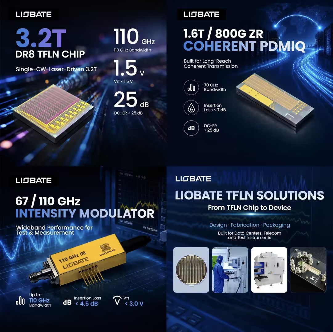
For LiDAR programs, Liobate focuses on three closely related areas:
l Relevant electro-optic building blocks. The TFLN device portfolio includes intensity modulators, phase modulators, and optical frequency comb devices for power control, chirp generation, and coherent multi-wavelength architectures.
l High-performance photonic device specifications. For instance, Liobate’s narrow-linewidth frequency-swept laser has an intrinsic linewidth of 200 Hz, chirp linearity of 99.93%, a sweep bandwidth of 8.2 GHz, and an output power of 8 dBm. These figures provide a concrete reference for high-coherence FMCW transmitter development.
l Device-to-package development. Custom chip tape-outs, packaged-device design, multi-channel configurations, and system-specific testing help align the optical chip with the laser, CMOS driver, coupling scheme, and environmental target.
As FMCW LiDAR moves toward compact, multi-channel products, the modulator must preserve chirp quality from the electrical waveform to the packaged optical output. Contact Liobate to discuss the modulation function, wavelength, channel count, test plan, and packaging configuration for your LiDAR design.


 The previous article
 Returns the list
 2026/11/11